Theory
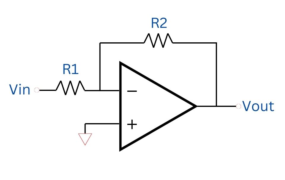
An inverting amplifier is a fundamental configuration in the field of operational amplifiers (op-amps). It is widely used in various electronic applications due to its ability to invert and amplify input signals. In this explanation, we will explore the theory behind an inverting amplifier using an op-amp, two resistors (R1 and R2), with the input voltage denoted as Vin and the output voltage as Vout.
Circuit Configuration
The inverting amplifier circuit consists of:
- Operational Amplifier (Op-Amp): The central component that amplifies the input signal.
- Resistors R1 and R2: These resistors set the gain of the amplifier.
In this configuration:
- The input voltage Vin is applied to the inverting input terminal (-) of the op-amp through resistor R1.
- The non-inverting input terminal (+) is connected to ground.
- The feedback loop connects the output Vout to the inverting input through resistor R2.
How It Works
- Input Stage: The input signal Vin is applied to the inverting input of the op-amp through resistor R1. The non-inverting input is grounded, creating a virtual ground at the inverting input due to the high gain of the op-amp.
- Feedback Loop: The output voltage Vout is fed back to the inverting input through resistor R2, forming a negative feedback loop.
- Current Flow: The current I flowing through R1 is the same as the current through R2, as the input impedance of the op-amp is very high, causing negligible current to flow into the inverting input.
- Voltage at Inverting Input: The voltage at the inverting input is virtually zero (virtual ground), leading to:
I = Vin / R1 = -Vout / R2
- Output Voltage Equation: Solving for Vout, we get:
Vout = -Vin × (R2 / R1)
This equation shows that the output voltage Vout is the input voltage Vin multiplied by the gain factor and inverted in phase, which is determined by resistors R1 and R2.
Gain of the Amplifier
The gain Av of an inverting amplifier is given by:
Av = -R2 / R1
This indicates that the output voltage is the input voltage scaled by the gain factor and inverted in phase. The gain can be adjusted by changing the values of resistors R1 and R2.
Summary
An inverting amplifier using an op-amp, two resistors R1 and R2, inverts and amplifies the input voltage Vin to the output voltage Vout.
The gain of the amplifier is -R2 / R1, making it a versatile and essential component in many electronic circuits. Understanding this theory is fundamental for designing effective amplification systems in various applications.
Mathematically, we can express the Inverting Amplifier equations as:
Vout = -Vin × (R2 / R1)
Vin = -Vout × (R1 / R2)
R1 = (-Vin / Vout) × R2
R2 = (-Vout / Vin) × R1
The Inverting Amplifier Calculator uses the equations above to find each parameter that's required as long as three out of four of the parameters are provided.
